
 Send Inquiry
Transformer winding deformation tester
Price 10000 USD ($)/ Unit
Transformer winding deformation tester Trade Information
- Minimum Order Quantity
- 1 Unit
- Supply Ability
- 10 Units Per Month
- Delivery Time
- 60 Days
About Transformer winding deformation tester
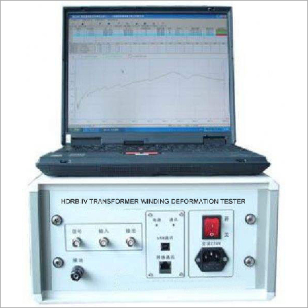
Transformer winding deformation tester
Description
- Transformer winding deformation tester is for checking deformation conditions of high voltage transformers.
- It adopts two methods to checking deformation conditions: scan-frequency method and low-voltage impedance method.
Main features
- Two checking methods, up-to-date technology
- No need to do any disassemblies for test, except for removing connecting busbar.
- Split style structure, connection between main instrument and computer can be via USB or Ethernet network, plug and play.
- All connectors have fault tolerance, site connection is safe and simple
- High intelligence level, equipped with self-adapting filter, automatic range adjusting, automatic sampling frequency adjusting.
- Adopts high speed high precision AD converter, good testing stability and repeatability, high testing accuracy, better than 0.1%
- Equipped with expert diagnosing system, automatic diagnose winding conditions
Specialty of testing software
- Adopts windows platform, compatible win9X/windows2000/winXP
- Loading 6 curves simultaneously, automatically calculate parameters of every curve, automatically diagnose deformation condition and provide conclusion for reference.
- Strong software managing function, automatically save ambient condition parameters, providing basis for diagnosing winding deformation; automatically saving testing data, color printing test reports.
- Humanistic software providing options for different conditions, no need many site inputs, convenient operation.
- High intelligent software, press one key to finish all the test works
Main parameters of scan-frequency measuring section
- Interface between instrument and PC: USB
- Exciting signal source: self-owned standard sine wave exciting signal, output range can be adjusted by software, max. range is +/-10V; output impedance is 50.
- Two high speed parallel AD converter channels, each max. sampling ratio is 20Msps
- Resolution of collecting channel: 12 bit
- Max. dynamic error of collecting channel: 0.5%
- Input impedance of collecting channel: 1M
- Measuring range: 1K-2MHz
- Scanning method: linear or logarithmic distribution
- Scanning frequency precision: frequency precision of output sine signal is not more than 0.01%
- Max. measuring dot: 3000 dots
Main parameters of low-voltage impedance measuring section
Voltage measuring index:
- Input voltage measuring range: 25V-500V (directly measuring); When doing impedance test, use AC240V or AC400V.
- Max. voltage: 600V
- Basic precision: 0.1%
- External potential transformer ratio: 1~10000
Current measuring index:
- Input current measuring range: 0.5-50A (directly measuring)
- Max. current: 50A
- Basic precision: 0.1%
- External current transformer ratio: 1~10000
- Impedance measuring range: 0~100%
- Impedance measuring precision: 0.1%
Power measuring index:
- Power measuring range: 15W~10kW
- Active power: 0.2% (power factor >0.5); 0.5% (power factor >0.01)
- Reactive power precision: 0.5%
- Apparent power precision: 0.5%
Power factor index:
- Measuring range: 0.000~+/-1.000
- Capacitive load: leading power factor
- Inductive load: lagging power factory
- Basic precision: 0.5%

Price:
- 50
- 100
- 200
- 250
- 500
- 1000+

More Products in Transformer Testing Equipment Category
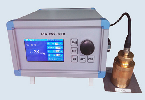
Electrical Silicon Steel Iron Loss Tester
Price 10000 USD ($) / Set
Minimum Order Quantity : 1 Unit
Output : Digital Display
Cooling Type : Air Cooling
Efficiency : High Precision Measurement
Rated Voltage : 220V AC
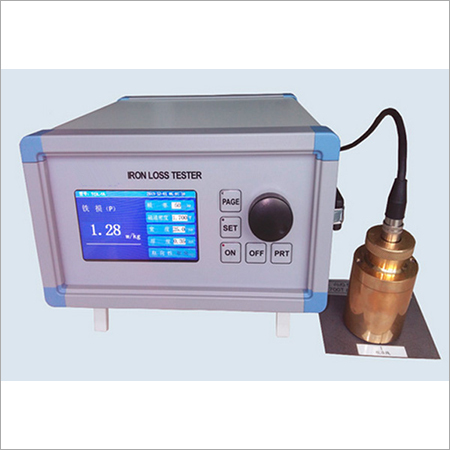
Electrical Silicon Steel Iron Loss Tester
Price 10000 USD ($) / Set
Minimum Order Quantity : 1 Unit
Output : Digital Display
Cooling Type : Air Cooling
Efficiency : High Efficiency Measurement
Rated Voltage : 220V

Impulse Voltage Generator For Power Transformer Testing
Price 10000 USD ($) / Set
Minimum Order Quantity : 1 Unit
Output : Impulse voltage waveform
Cooling Type : Air Cooled
Efficiency : 98%
Rated Voltage : Up to 1800 kV impulse

Partial Discharge Test Equipment For Power Transformer Testing
Price 10000 USD ($) / Set
Minimum Order Quantity : 1 Unit
Output : Digital Display, Analog Output Option
Cooling Type : Oil Cooled or Air Cooled
Efficiency : High, >98%
Rated Voltage : Up to 100 kV


Developed and Managed by Infocom Network Private Limited.
